The importance of seals in check valves
July 8, 2020
The new catalogue: valves and hydraulic accessories – is ready!
October 19, 2020
When producing a hydraulic circuit, considering head loss is fundamental because system performance depends also on containing it. Every distribution network requires the guarantee of a specific head at the outlets, and this can be obtained thanks to a balanced system without any points that are more disadvantaged than others.
Head loss is the difference in pressure between two points in a circuit.
Pressure drops caused by resistances that oppose the movement of a fluid obviously occur with viscous liquids. Fluid viscosity represents friction that generates energy dissipation, therefore decreased pressure. In this case, we are talking about continual or distributed head loss in all the pipes.
In addition to continual head loss, though, localised head loss also exists, where the liquid meets obstacles because it has to change direction or because the surface over which it flows changes. Localised head loss occurs, for example, at mouthpieces, adapters, elbows, but also with mechanical elements such as filters or valves.
How to read a valve head loss graph
Take, for example, the case of a drop in pressure that occurs when the fluid meets a hydraulic valve. Head loss graphs come from the interpolation of the flow rate data (x axis) and the decrease in pressure (y axis) caused when the circulating fluid crosses a system component.
To create the curve that represents the head loss of a valve, the pressure is measured by gauges positioned at the valve entry and exit points. Readings are taken at increasing flow rates until a head loss of 1 bar is identified. At this point the Kv (or flow) coefficient can be defined, which specifies the flow rate, expressed in m3/h, that generates a head loss of 1 bar when passing through the valve. It is an important value because by combining the valve flow rate with the head loss makes it possible to correctly size the system, so avoiding serious errors that can compromise operation.
When the valve guarantees the smallest head loss
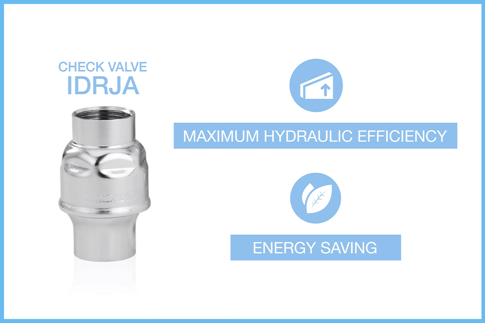
Let’s compare three one-inch check valves: RE-GE, Cromax Ap and Idrja. The first is a brass valve that guarantees a Kv of 13.8 m3/h. The stainless steel Cromax Ap valve, designed to resist high pressures, instead has a Kv of 12.7 m3/h. Finally, the stainless steel Idrja valve. In this case the flow coefficient is 18.7 m3/h, a value that is from 35% to 47% greater than the other two. This is possible because Idrja is a check valve that was studied precisely to offer maximum hydraulic efficiency.Its large, smooth flow surface, the care taken with the construction details, the slimness of the stainless steel walls and TIG welding favour the flow of liquids and reduce friction sources. All this turns into minimum head loss – and consequently, as can easily be imagined, energy savings – to guarantee the flow rate and pressure demanded by our system.
Discover our check valves Idrja


